Practical 1: Local Illumination Models
- Practical sources
- GLSL Specifications
- OpenGL 4.4 API Quick Reference Card (download it, keep it)
The deadline for giving back TP1 is: Tuesday, November 8th (midnight, European Time)
Code structure
First, uncompress the archive.
Change your working directory to OpenGL_TP, and use the shell commands qmake-qt5, followed by make (you can also use the GUI qtcreator).
The compiler should return after a few warnings (but no errors). The command ./viewer/myViewer starts the actual viewer. It should look like the picture below. The program has 3 windows: the main window with the OpenGL display, an auxiliary window with the parameters, and the third with the menus:
- File menu: to change the geometric model displayed, the texture or the environment map. It also lets you save a screenshot of the program.
- Window size menu: to change the size of the window.
- Shaders menu: to change the shader used to display the object. For the time being, all shaders are minimalists, returning flat color. Your work will be writing these shaders.

The code C++ contains:
- An auxiliary library, trimesh2, in charge of loading the model file and converting it into a data structure for display. It can read ply, obj, 3ds, off files, and many others. There are several models in the archive, but feel free to add your own.
- The main.cpp file in charge of starting the application and setting up the menus.
- The OpenGLWindow class, just to create a Qt window with an OpenGL context.
- The GlShaderWindow class, derived from OpenGLWindow, where most of the work happens: loading the scene, compiling the shaders, send parameters to the shaders, etc.
For almost all practicals and exercises (except for shadow maps, in Practical 3), you shouldn't have to change anything in the C++ source files. You might need to open them to know the parameters names.
The Shaders menu is automatically generated from the Qt resource core-profile.qrc. Shaders are displayed in alphabetical order, except those whose name begins with h_ (for hidden). Each shader has a vertex shader, shader.vert, and a fragment shader, shader.frag.
Phong model
Your first work will be to edit the shader 2_phong to implement the Phong local reflection model, with ambiant, diffuse and specular lighting.
In the vertex shader, you have a 3 transformation matrices, matrix, perspective and normalMatrix. The first two contain the transformation from object coordinates to screen coordinates. The last one does the same transformation for normals.
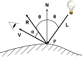
For each vertex, you have 3 variables: vertex, normal et color. You also have the light source position, lightPosition and a boolean noColor, telling whether the model has vertex color information.
You work is to compute the lighting. It starts with compute the vectors you will need: the normal at that point, the vector, direction from the point to the light source, the vector, direction from the point to the camera.
C being the point color, I being the light source intensity, the lighting components are defined by:
- Ambient lighting:
...
with the ambiant reflection coefficient (you can choose it freely, usually 0.2)
- Diffuse lighting:
...
with the diffuse reflection coefficient (again, you can choose it freely, usually from 0.4 to 0.7).
- Specular lighting:
with the specular reflection coefficient (again, you can choose it freely) and s the object shininess.
The object color will be .
Phong shading in the fragment shader
Write a fragment shader computing Phong shading. You will have to pass certain variables from the vertex shader to the fragment shader. They will be linearly interpolated; remember that you have to normalize them.
To debug the program, display each lighting component separately: ambient alone, diffuse alone, specular alone, then combine them together.
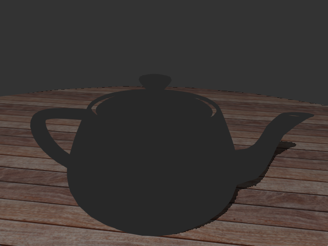 |
+ | 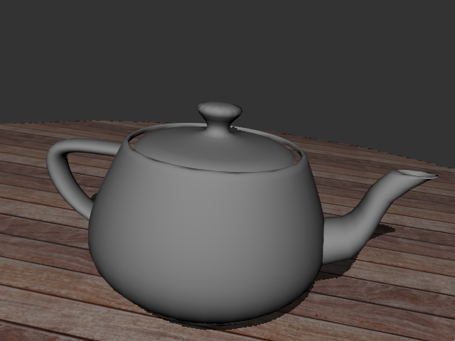 |
+ | 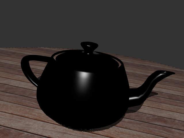 |
= | 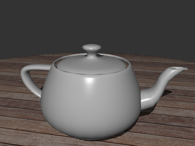 |
| Ambient | + | Diffuse | + | Specular | = | Together |
Blinn-Phong shading
Rewrite the previous shader to have a Blinn-Phong shading. This time, the specular component is defined by:
where is the half-vector between the view direction vector and the light direction vector :
You should get (almost) the same picture as with Phong shading if you multiply the shininess exponent s by 4. The graphical user interface (through the auxiliary window) gives you two useful parameters:
- blinnPhong, a boolean. Tells whether we should display using the Phong model or the Blinn-Phong model.
- shininess, a float, the exponent for the specular component for Phong shading.
Fresnel Coefficients
The intensity of the specular component depends on the Fresnel coefficient, F, itself a function of the viewing direction and the index of refraction of the material, :
with:
Rewrite your shader so that the specular color is multiplied by the Fresnel coefficient, F. The user interface gives the varying parameter eta (a float, strictly positive).
When is the Fresnel coefficient most visible? When is the specular component most visible?
If the math formulas in this page appear as garbage, force your browser to use UTF-8, and reload the page.